Through Deck Swivel Applications, swinging about the mooring, Swivel Stack
The first five Diagrams show how the ship swings about each case described in the previous section, Applications. The Area that each swings is shown as a composite birds eye view in the last diagram, this also elaborates why some positions are chosen that minimise swing in termrs of rotation or area occupied.
.png "1, Swinging about Midships")
1, Swinging about Midships
.png "2, Swinging about Bow")
2, Swinging about Bow
.png "3, Swinging in Bow")
3, Swinging in Bow
.png "4, Swinging Infront Bow")
4, Swinging Infront Bow
.png "5, Swinging away fron Bow")
5, Swinging away fron Bow
.png "6, Composite Area of Swing")
6, Composite Area of Swing
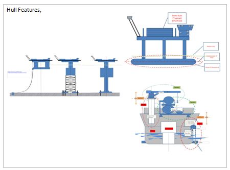
Swivel Restraints
The three Diagrams illustrate some of the restraints experience using swivels. The first is a simplified arrangement of a through deck application. The through deck penetration is a tube that goes from keel base to top of tank deck. Contaned in this tube is the swivel column which keeps in line with the subsea arrangement whilst the swivel column rotates with the ship. the swivel column rotates in bearings at its top and towards the bottom ends. This behaves like an axle in a bearing on its lower end it has forces froom the weight of the sub sea flow lines, the weight from the mooring arrangement and its retention of sideways movement from current, wave and wind. These are large forces and they are taken into the ship skin and frames which are not necessarily thick sections.
.png "1, Swivel, Thrudeck, Section")
1, Swivel, Thrudeck, Section
.png "2, Thrudeck Base Plate to Tube Can")
2, Thrudeck Base Plate to Tube Can
.png "3, Can for Thrudeck Tube Can")
3, Can for Thrudeck Tube Can
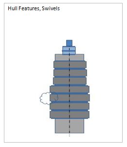
What happens at the Swivel
The first Diagram shows a typical Swivel Stack. Swivel Stacks, Through Deck or Cone are somewhat similar. The stack is the manner of transferring media from sub sea to ship through a rotating connection. Only one axial conection can be made at the top the swivel stack handles the rest through a series of seals stacked on one another. These have an annular circular passage often referred to as a Torroid or toroidal passage. These cans are complex since they contain seal systems that may have pressures to 800 bar or possibly more. The second diagram shows a section through a stack looking at the toroidal passage end on. The last three diagrams show how the flows come into the fixed column, flow around the toroidal passage and exit at the centrline that the ship may have taken up.
.png "1, Swivel Stack, Elements")
1, Swivel Stack, Elements
.png "2, Section, Plan of Element")
2, Section, Plan of Element
.png "3, Fluid Path ,Ship Ahead")
3, Fluid Path ,Ship Ahead
.png "5, Fluid Path, Ship 30 deg Stbd")
5, Fluid Path, Ship 30 deg Stbd
.png "6, Fluid Path. Ship 60 deg Stbd")
6, Fluid Path. Ship 60 deg Stbd
C2V Where you see this, Click too View
C2V
C2V
C2V
C2V
Index, Section 2 Supports,
C2V
C2V Where you see this, Click too View
C2V
C2V
C2V
C2V
C2V
C2V
C2V
C2V
C2V
C2V
C2V
C2V
C2V
C2V
MODULEitus
a general understanding of Modules
Level 2
Level 3
C2V, > Go to view series
C2V, > Go to view series
C2V, > Go to view series


.jpg "1, Swinging about Midships")
.jpg "2, Swinging about Bow")
.jpg "3, Swinging in Bow")
.jpg "4, Swinging Infront Bow")
.jpg "5, Swinging away fron Bow")
.jpg "6, Composite Area of Swing")
.jpg "1, Swivel, Thrudeck, Section")
.jpg "2, Thrudeck Base Plate to Tube Can")
.jpg "3, Can for Thrudeck Tube Can")
.jpg "1, Swivel Stack, Elements")
.jpg "2, Section, Plan of Element")
.jpg "3, Fluid Path ,Ship Ahead")
.jpg "5, Fluid Path, Ship 30 deg Stbd")
.jpg "6, Fluid Path. Ship 60 deg Stbd")