The first example of a Power Generation Installation is Magnus, using Gas Turbines. This has been chosen as it provides an introduction on
the choice of GT drivers that may be used. This platform was from the 80,s and also illustrates the choice of driver made then ( industrial ) and
later the prefernce for Aero Derivative. The 1st Picture illustrates the structural choices being made to accomodate the GE Frame 5 Industrial
Turbine selected for Power Generation. The use of Aero Derivatives was in its infancy and the choice to use Frame 5,s were reliability and
longitudity . Figure 1, the first Picture illustrates the structural choices being made to accommodate the GE Frame 5 Industrial Turbine selected
for Power Generation. The GE Frame 5 has a rigid bed and to ensure it was not compromised the structural requirement was made that no
point loads were to progress from the module frame to the machine. Likewise no point loads were to progress from the MSF to the Module and
this approach was repeated to jacket to MSF. The outcomes which became very contractual was that to ensure loads were not transmitted to
the Machine all substructure became overly robust or putting simply heavy. Magnus already with growing weight implications became even
more compromised in this respect. The second picture is the piping model of the Module, this was a structuarl box of som 2000 te. It shows 2
trains, the inlet filtration and exhaust stacks on one end, the other end shows the control rooms which in themselves were modules. The end
bay of the Module was designed so that the control Room of different discip[lne could be constructed elsewhere and slipped into the Module. All
that remained was the hook up from the GT's output terminal blocks and the hook up link to the platform electrical systems. Picture 3 looks
into one of the power generation Control Rooms. These were modular and based on the Road Transport dimension of an ISO 20 container,
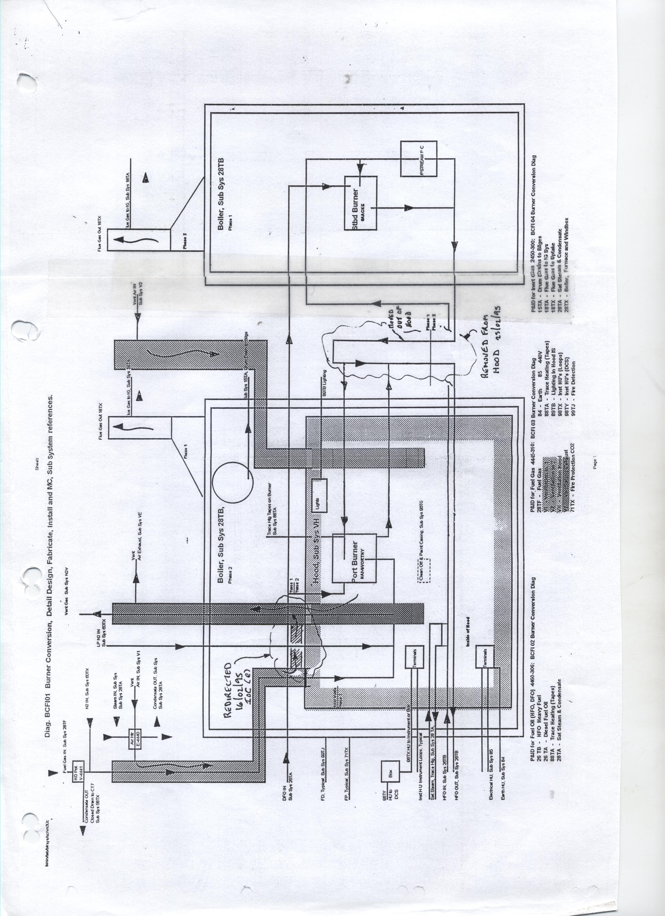
These Diagrams show the build of a GE Frame 5 GT and its mounting base. This gas turbine generator train for Magnus was built up in GE
John Browns workshop in Glasgow. Once built the whole power train could be workshop tested. During the start of the first test there was a
blade rub due to missmatched blades and thermal growth. Gas turbines are made up of series of blades which are bedded in a shaft, they
have complex interlocking roots, the blade growing out of the shaft tree like. On run up shaft and tree grow and precision components are a
necessity for efficienf running. Once established they will perform for a considerable length of time as opposed to the definitive period, approx.
a year for the aero deravative machine. Once tested the GT and its local enclousures become a modulewhich inturn is mounted on the base
of the topside Module. The lastl of a module which contains 2 machines, the gross weight being some 2000 te. The C2V goes to the GE
Site and shows the detail and style of an aeroderavative verses industial machine.


.jpg "4 Machine under Build")


.jpg "Magnus Bed Steel (FILEminimizer)")
.jpg "magnus 002 2 (FILEminimizer)")
